Retaining wall is a structure which is used to retain or hold back any material, usually soil, and prevent it from sliding away. In this post, we shall see about the various components and types of retaining wall and their behaviour and type of loads on retaining wall.
Page Contents
TYPES OF RETAINING WALL
The retaining walls are of many types and each one behaves differently under the lateral pressure, thus different design approach is adopted for each. The following are the different types of retaining walls.
1. Gravity retaining wall
2. Cantilever retaining wall
3. Gabion retaining wall
4. Counter-fort retaining wall
5. Buttress retaining wall
6. Piled retaining wall
Of these, Cantilever retaining wall is most common. So, we shall see the structural behaviour of cantilever retaining wall in detail about it. This type is adopted when the depth of the retained earth is less than 6m.
COMPONENTS OF CANTILEVER RETAINING WALL
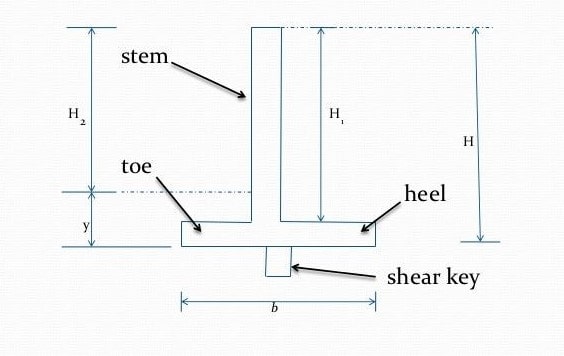
A typical cantilever retaining wall consists of three elements.

a. Stem
b. Base slab
c. Shear key
Base slab is further divided as
i) Heel slab (the portion of the base slab present on the backfill side)
ii) Toe slab (the portion of the base slab present on the other side)
LOADS ON RETAINING WALL
Before we understand the behaviour of each component, we need to know different loads that would be acting on the Retaining Wall.
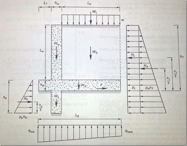
1. Earth Pressure
a) Active earth pressure
The earth retained by the wall exerts a lateral (horizontal) load on the stem part of the structure. This lateral load depends on the height of the retained soil and soil properties like unit weight and angle of repose.
b) Passive earth pressure
The earth available on the other side of the stem exerts some lateral pressure on the stem, opposite in direction to the active earth pressure.
Usually, this load is not considered to make the design more conservative. But if the system fails by sliding, a shear key is provided, then this load will be considered.
This post of ours explains how to assign soil pressure in standard software like SAP2000 or ETABS

2. Surcharge load
Sometimes, additional load acts on top of the retained soil. This is called Surcharge Load. It increases the lateral load on the stem and also acts as a gravity load on the heel.
3. Bearing pressure
The soil below the retaining wall exerts a bearing pressure on the bottom face of the base slab. This pressure is due to the combination of gravity load and the resultant rotating moment acting on the system.
MODES OF FAILURE
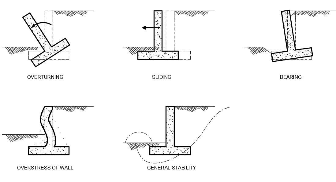
The following are the different modes of failure that is expected in a Cantilever Retaining Wall.
1. OVERTURNING FAILURE
The lateral pressure acting on the system tends to rotate the system about the toe. This moment is called the overturning moment. This should be resisted by the self-weight of the system.
The weight of the retained soil also contributes to resisting the overturning moment. For safety, the ratio of the resisting moment to overturning moment should be more than 1.5.
2. SLIDING FAILURE
The lateral force acting on the system tries to push the system in a direction away from the retained soil. If the friction (developed by the soil) at the bottom of the base slab is not sufficient, then the structure tends to slide.
This friction developed, depends on the self-weight and weight of the retained soil. For safety against sliding, the ratio of Frictional force to lateral force should be more than 2.
If the system fails to achieve this value, the shear key can be provided at the base. The passive pressure acting on the shear key will help to resist the sliding.
3. BEARING PRESSURE FAILURE
The bearing pressure developed at the base of the system should be less than the bearing capacity of the soil. If it exceeds, then the soil loses its capacity to hold the structure.
Also, the bearing pressure should be completely compressive in nature, avoiding eccentricity. The resultant force of lateral and gravity loads should act within the core of the system, such that, no tensile pressure is developed below the base.
4. OVERSTRESS OF ELEMENTS
If the size i.e., the thickness of the elements and the tensile reinforcement is insufficient, the elements will be overstressed and fails.

The following segment will help to understand the behaviour of each element and to find the location and position of reinforcement bars.
BEHAVIOUR OF ELEMENTS
1. STEM
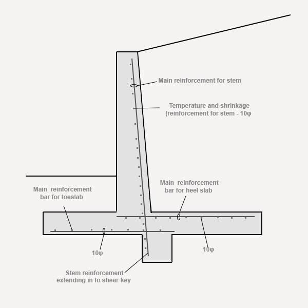
The stem is free at the top end and fixed at the base. The lateral pressures make the stem to bend away from the retained soil. Hence, the stem is treated as a vertical cantilever and designed for the maximum bending moment at the base. Tension is developed in the face near the retained soil. The tensile steel calculated will be placed in the tensile zone as vertical bars. The horizontal steel is distribution steel.
2. HEEL SLAB
The heel is also considered as a cantilever slab. As we know, the heel is subjected to surcharge load, the weight of retained soil from the top and soil bearing pressure from the bottom.
Since, the structure is used to retain soil of larger depth, the effect of soil weight on the heel will be more when compared to bearing pressure. Thus, the heel bends downward. Hence, tension is developed on the top surface.
Therefore, the tensile steel should be provided on the top and in the direction perpendicular to the stem. Distribution steel will be provided in the other direction.
3. TOE SLAB
The effect of the weight of soil above the toe slab will be less when compared to the bearing pressure and hence the toe slab bends upward. Toe slab is also designed as a cantilever slab.
Since the slab bends upward, tension is developed on the bottom surface. Hence, the tension steel is provided at the bottom surface perpendicular to the stem.
4. SHEAR KEY
The major purpose of the shear key is to resist the structure from sliding. It is designed as the cantilever slab too.
It will be subjected to passive soil pressure. This will bend the shear key away from the direction of the sliding. Hence, the tensile bar is provided on the left face (as per the picture) of the shear key in the vertical direction.
Reinforcement details are shown in the figure below.

